Experiments
-
Experiments
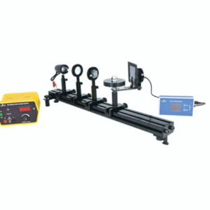
Atomic Spectra Experiment
OBJECTIVES
- To understand the concept of diffraction of light.
- To measure and analyze the emission spectral lines of different elements.
PRINCIPLE
The source of electromagnetic radiation is atoms. When the atoms of an element are in an excited state, they return to a lower energy state by emitting electromagnetic (EM) radiation. The transition of the electrons in the atom from a higher energy level to lower unique energy levels for the occupation of electrons, due to this the EM spectrum emitted is a unique signature of an element or a substance. The study of the characteristics of EM radiation emitted by atoms is called Atomic Emission Spectroscopy.
KEY FEATURES
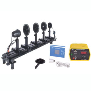
- Precise Optical Alignment: The optical alignment of the components is attained by the optical bench, the set-up time is faster and experimentation is easy.
- Rotating table with On-board Telescope: The telescope on the rotating table is mounted with bearings for smooth rotation. The diffraction grating mounted is mounted at the center of the rotating table. The telescope is easy to focus on and operate. The angle of the rotating arm has a least count of 0.1° for accurate measurement of the spectral lines.
- Power Supply Built in the Discharge Tube Holder: The built-in power supply makes a more compact system with easier changing of the discharge tubes. Easy power connection and no unnecessary wire intrusions
WHAT YOU NEED
- OB1 Optical Bench Set 0.8m 1
- HA010 Converging Lens Holder 1
- HA012 Adjustable Collimating Slit Holder 1
- UP040 Spectrum Tube Power Supply Assembly 1
- UP035 Telescope Assembly 1
- AC018 Diffraction Grating 1
- AC021 Spectrum Tube, Hydrogen 1
- AC022 Spectrum Tube, Helium 1
- AC023 Spectrum Tube, Mercury 1
- AC024 Spectrum Tube, Krypton 1
- AC025 Spectrum Tube, Argon 1
Complete Equipment Set with Instruction Manual from catalogue.
ASE1-C -
Experiments
Brewster Angle Experiment
OBJECTIVES
Measurement of Brewster’s angle for a given dielectric dispersive medium.
PRINCIPLE
When un-polarized light is incident on the surface of a dielectric (such as a glass), at a certain angle of incidence the reflected light is completely plane-polarized. This phenomenon was discovered by Sir David Brewster and, thus, the specific angle is called Brewster’s angle or polarization angle. Also, from the experiment, it can be confirmed that the reflected ray and the refracted ray are 90° apart when the incident angle is set at Brewster’s angle.
KEY FEATURES
- Rotating Table: A simple, smooth, and compact rotating table. The rotating table used is extremely smooth to operate. It is a single assembly that holds a glass sample, analyzer, and light sensor, thus minimizing the size of the whole equipment. Smooth rotation makes measurement continuous and accurate.
- Light Sensor: This enables the measurement of light intensity at various angles of reflection. The meter reads with a precision of 1 lux. The Lux meter helps obtain a continuous smooth curve of angle vs intensity and determines the Brewster angle much more accurately than the manual method.
WHAT YOU NEED
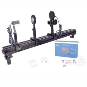
- OB1 Optical Bench Set 0.8m 1
- HA001 Light Source Holder 1
- HA010 Converging Lense Holder
- HA012 Adjustable Collimating Slit Holder 1
- UP030 Rotating Table Assembly 1
- AC002 Analyzer Square 1
- HA511 Light Sensor Holder 1
- PH61022D/2 Power Supply for Light Source 1
- AC004 Glass Block 1
- DP1 Data Processor 1
Complete Equipment Set with Instruction Manual from catalogue.
BAE1-C -
Experiments
BH Curve Experiment
Objectives
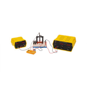
To observe and study the magnetization behaviour of the ferromagnetic magnetic materials provided.
Principle
The B-H curve is the curve characteristic of the magnetic properties of a material or element or alloy. It tells you how the material responds to an external magnetic field, and is a critical piece of information when designing magnetic circuits. A Ferromagnetic material, retains its magnetization even after the external magnetic field is removed. And the reversal or change in the direction of the applied external magnetic field results in a change in the magnetization of the ferromagnetic material. It is seen that the change in the magnetization lags behind the change in the applied external magnetic field. Thereby, a hysteresis behaviour is exhibited.
Key Features
- Compact Setup – The apparatus design is compact and yet effective to perform the experiments with ease. The simple connections and stand to hold the teslameter probe, makes it easy to handle.
- Multiple samples included – Multiple ferromagnetic samples are provided to study the BH curves of the different materials. The removable cores make it easy to change between samples.
Equipments Needed for the Experiment
- PH94014 B- H Curve Measuring Apparatus 1
- PH64505 Multimeter 1
- PH61035D/5 Advanced Power Supply 1
- PH93240 Teslameter 1
BHC1-C -
Experiments
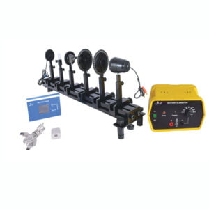
Beer Lambert’s Law Experiment
Objectives
To find the concentration of a liquid using the samples of known concentration using Beer Lambert’s Law.
Principle
Beer Lambert’s law relates the attenuation of light through a substance and the properties of that substance. Light interacts with matter in the following ways: emission, absorption, transmission, and reflection or scattering. Depending on the physical and chemical properties of the matter under interaction, there can be one or more ways in which light interacts. It is because of these interactions light can be used as a probe to measure the physical and chemical properties of materials.
Key Features
- Precise Optical Alignment: The optical alignment of the components is attained by the optical bench, the setting up time is faster and experimentation is easy.
- Digital Lux Meter: This enables the measurement of light intensity at various angles of reflection. The meter reads with a precision of 1 lux.
What You Need
OB1 Optical Bench Set 0.8m 1 UP001 Upright 2 HA001 Light Source Holder 1 HA004 Polarizer Holder 1 HA006 Analyzer Holder 1 HA012 Adjustable Collimating Slit Holder 1 HA025 Cuvette Holder 1 HA510 Light Sensor Holder 1 DP1 Data Processor 1 PH61022D/2 Power Supply for Light Source 1 AC006 Glass Cuvette 1 Complete Equipment Set with Instruction Manual from catalogue.
BLL1-C -
Experiments
Biot-Savart’s Law Experiment
OBJECTIVES
- Measuring the magnetic field of a straight conductor and of circular conductor loops as a function of the current.
- Measuring the magnetic field of a straight conductor as a function of the distance from the axis of the conductor.
- Measuring the magnetic field of circular conductor loops as a function of the loop radius and the distance from the loop.
PRINCIPLE
Electric currents generate magnetic fields. Biot–Savart law is an equation describing the magnetic field generated by a constant electric current. It relates the magnetic field to the magnitude, direction, length, and proximity of the electric current. In this experiment, we study the magnetic field characteristics in the straight conductors and different types of circular coils.KEY FEATURES
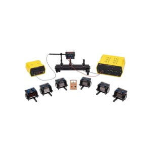
- Multiple coil variants: The equipment comprises a variety of coils to carry out experiments. One can study Biot Savant law for a straight conductor, coils of variable length, density, and a number of turns. All coils are mounted on a common horizontal bench and upright system.
- 2-axis Teslameter: The equipment is provided with a teslameter with probes to measure both axial and tangential directions. A square shaft mount is provided for the accurate mounting of the probes.
WHAT YOU NEED
- OB2 Optical Bench Set 0.4m 1
- HA015 Solenoid with Variable Turns 1
- HA016 Solenoid with Variable Lengths 1
- HA017 Solenoid with Different Winding Density (Set) 1
- HA018 Straight Conductor Holder 1
- PH93240 Teslameter, With Axial and Tangential Hall Probe 1
- PH61035D/5 Power Supply 1
Complete Equipment Set with Instruction Manual from catalogue.
BSL1-C -
Experiments
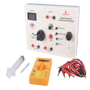
Energy Band Gap Experiment
OBJECTIVES
To find the energy band gaps for different semiconductor diodes and LEDs
PRINCIPLE
At an absolute zero-degree temperature, semiconductors are pure insulators. As the temperature is increased thermal energy creates vibrations in the crystal lattice and a few electrons, which acquire sufficient vibrational energy break their covalent bond, become free, and move to the conduction band. The energy required to rapture the covalent bond is designated as energy gap EG and termed as energy gap or band gap energy.
KEY FEATURES
- Built-In Heater: The heating element is built into the system and is powered by 12V input. The efficient heating mechanism heats the system to the required temperature in a few minutes with a minimum power requirement of 40W.
- Modular Design: The modular design of the setup allows the testing of multiple diodes as well as different LEDs.
- Built-In Voltage and Temperature Probe: All the necessary parameters to be measured are available directly on the setup itself.
WHAT YOU NEED
PH94002 Energy Band Gap Apparatus 1 PH61035D/5 Power Supply 1 PH64505 Multimeter 1 AC026 Syringe, 20ml 1 AC028 Silicone Oil, 50ml 1 Complete Equipment Set with Instruction Manual from catalogue.
EBG1-C -
Experiments
Faraday Effect Experiment
OBJECTIVES
- Observe the effect of a magnetic field on the plane of polarization of polarized light as it passes through a dispersive medium.
- Measure the Verdet’s constant of a given dispersive material.
PRINCIPLE
When linearly polarized light passes through an optical medium in a region of the strong magnetic field, the plane of polarization of linearly polarized light rotates by an angle. The angle of rotation of plane-polarized light is proportional to the length of the optical medium and component of the magnetic field in the direction of light. The factor of proportionality is medium-specific and is called Verdet’s constant and this effect is known as the Faraday Rotation or Faraday Effect. Discovered by Michael Faraday in 1845, the Faraday effect was the first experimental evidence that light and electromagnetism are related. In the experimental setup, the optical medium is an SF6 glass cube.
KEY FEATURES
- Modular U- Core design with precise optical alignment – U-Core along with pole pieces are designed with the Poka-Yoke principle so that the optical alignment is undisturbed when the pole pieces are moved to accommodate samples of different dimensions.
- Light Sensor- This enables measurement of light intensity which in turn helps in measuring the amount of rotation of plane polarization. The meter reads with a precision of 1 lux. Sensor-based measurements eliminate the errors in values due to simple eyesight measurement. Moreover, it provides the freedom to conduct the experiment at any setting of polarizer-analyzer angles.
WHAT YOU NEED
- OB1 Optical Bench Set 0.8m 1
- HA001 Light Source Holder 1
- HA004 Polarizer Holder 1
- HA006 Analyzer Holder 1
- UP025 Electromagnet Set Assembly 1
- AC004 Glass Block 1
- HA510 Light Sensor Holder 1
- PH93225G Gauss Meter 1
- PH61035D/7 Power Supply for Electromagnet 1
- PH61022D/2 Power Supply for Light Source 1
- DP1 Data Processor 1
- DPS01 DP Switch 1
Complete Equipment Set with Instruction Manual from catalogue.
FEE1-C -
Experiments
Malus Law Experiment
OBJECTIVES
- To experimentally verify malus’s law.
PRINCIPLE
Light, when modeled as a wave phenomenon, can be classified as a transverse electromagnetic wave consisting of oscillating electric and magnetic fields that are oriented perpendicular to each other. Depending on the orientation of the plane of polarization of the electric field with respect to the direction of propagation of the wave, the wave can be classified as polarized or un-polarized. To measure the variation of transmission of an EM wave through two polarizers as a function of the angle of orientation between them and prove Malus’s Law.KEY FEATURES
- Precise Optical Alignment: The optical alignment of the components is attained by the optical bench, the set-up time is faster and experimentation is easy.
- Easy Analyzer Movement: The design of the analyzer helps for easier rotation without disturbing the optical alignment. The least count of 1° aid for more accurate readings.
- Digital Lux Meter: A digital lux meter enables the measurement of light intensity for each rotation of the analyzer. The least count of 1 Lux provides accurate readings.
WHAT YOU NEED
- OB2 Optical Bench Set 0.4m 1
- HA001 Light Source Holder 1
- HA004 Polarizer Holder 1
- HA006 Analyzer Holder 1
- HA510 Light Sensor Holder 1
- PH61022D/2 Power Supply for Light Source 1
- DP1 Data Processor 1
Complete Equipment Set with Instruction Manual from catalogue.
MLE1-C -
Experiments, Higher Science
Millikan Oil Drop Apparatus
Supertek’s Millikan Oil Drop Apparatus is a contemporary version of the classic design which allows the students to observe the velocity of an oil drop rising and falling in an electric filed. The apparatus is equipped with camera which allows the user to connect it with the computer screen for an easy viewing of the droplets. It permits the calculation of the force acting on the charge carried by the oil drop.
What’s Included
1x Millikan Oil Drop Apparatus
1x Non-Volatile Oil
1x Multimeter
1x StopwatchExperiments
To determine the charge of an electron by Millikan’s Oil Drop MethodMLK1-C -
Experiments
Photoconductivity Experiment
Objectives
To study the photoconductivity of CdS Photoresistor, in the following conditions:
- Applied voltage vs photocurrent (IPH) at constant irradiance (Φ).
- Photocurrent (IPH) vs irradiance (Φ) at a constant applied voltage (V).
Principle
The phenomenon of photoconductivity occurs when an incident light shown upon a semiconductor causes an increase in its electrical conductivity. This is because of the excitation of electrons across the energy gap into the conduction band, which leads to an increase in the number of free carriers in the conduction band, hence, an increase in the conductivity of the semiconductor. Here, we can study the characteristics of the CdS photoresistor under different conditions of light intensity and applied voltage.
KEY FEATURES
- Precise Optical Alignment: The optical alignment of the components is attained by the optical bench, the set-up time is faster and experimentation is easy.
- Fine and Easy Light Intensity Adjustment: Light intensity adjustment is done via the use of two polarizers. This helps in easier and fine light intensity adjustments.
- Simple and Easy Connections: The color-coded terminals on the various components aid in the ease of connections thus reducing the setup time.
WHAT YOU NEED
- OB2 Optical Bench Set 0.4m 1
- HA001 Light Source Holder 1
- HA004 Polarizer Holder 1
- HA006 Analyzer Holder 1
- HA020 LDR Module Holder 1
- PH61022D/20 Power Supply, 0-15V, 200mA 1
- PH61022D/2 Power Supply for Light Source 1
- PCE1-C: Complete Equipment Set With Instruction Manual
PCE1-C -
Experiments
Pin Diode Characteristics Experiment
OBJECTIVES
- To study the response of PIN diode, in the following conditions:
- Photocurrent (Iph) vs Applied voltage at constant irradiance (Φ) under Reverse biased condition of the PIN diode.
- Current (I) vs Voltage (V) under forward bias condition of the PIN diode.
PRINCIPLE
The PN-Junction diodes, though versatile, have a few limitations regarding the amount of current they could handle before breakdown and also have low switching frequency, low power handling capacity, and low quantum efficiency. To overcome all these issues PIN diode was designed. PIN diodes are also extensively used as photodiodes in PIN photodiode configuration and are very important in optical fiber communication.
KEY FEATURES
- Precise Optical Alignment: The optical alignment of the components is attained by the optical bench, the set-up time is faster and experimentation is easy.
- Fine and Easy Light Intensity Adjustment: Light intensity adjustment is done via the use of two polarizers. This helps in easier and fine light intensity adjustments.
- Simple and Easy Connections: The color-coded terminals on the various components aid in the ease of connections thus reducing the setup time.
WHAT YOU NEED
- OB2 Optical Bench Set 0.4m 1
- HA001 Light Source Holder 1
- HA004 Polarizer Holder 1
- HA006 Analyzer Holder 1
- HA021 Photodiode Module Holder 1
- PH64505 Multimeter 1
- PH61022D/2 Power Supply for Light Source 2
Complete Equipment Set with Instruction Manual from catalogue.
PIN1-C -
Experiments
Planck Constant Experiment
OBJECTIVES
To determine Planck’s constant using LED.
PRINCIPLE
KEY FEATURES- Built-In Heater: The heating element is built into the system and is powered by 12V input. The efficient heating mechanism heats the system to the required temperature in a few minutes with a minimum power requirement of 40W.
- Modular Design: The modular design of the setup allows the testing of different colored LED’s.
- Built-In Voltage and Temperature Probe: All the necessary parameters to be measured are available directly on the setup itself.
WHAT YOU NEED
PH94004 Planck Constant Apparatus 1 PH61035D/5 Power Supply 1 PH64505 Multimeter 1 AC026 Syringe, 20ml 1 AC028 Silicone Oil, 50ml 1 Complete Equipment Set with Instruction Manual from catalogue.
PLC1-C -
Experiments
Quinck’s Tube Experiment
Objectives
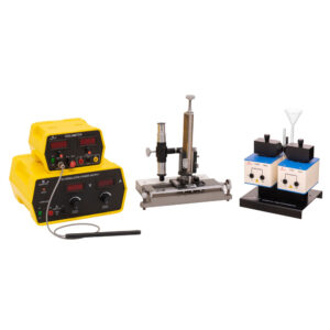
To measure the magnetic susceptibility of a given paramagnetic sample (FeCl3).
Principle
The Quinck’s method is used to determine magnetic susceptibility of diamagnetic or paramagnetic substances in the form of a liquid or an aqueous solution. When an object is placed in a magnetic field, a magnetic moment is induced in it. Magnetic susceptibility x is the ratio of the magnetization I (magnetic moment per unit volume) to the applied magnetizing field intensity H. The magnetic moment can be measured either by force methods, which involve the measurement of the force exerted on the sample by an inhomogeneous magnetic field or induction
methods where the voltage induced in an electrical circuit is measured by varying magnetic moment.Key Features
- Compact Setup – The apparatus design is compact and yet effective to perform the experiments with ease. The simple connections and stand to hold the teslameter probe, makes it easy to handle.
- Custom Quinck’s Tube – Specially designed quinck’s tube can be attached seamlessly on the setup and dimensions are controlled such that it fits perfectly between the pole pieces.
Equipments Needed for the Experiment
- PH94012 Electromagnet for Quinck’s Tube 1
- AC030 Quinck’s Tube 1
- PH61035D/7 Power Supply for Electromagnet 1
- PH93225G Teslameter, Digital 1
- PH30780 Vernier Microscope 1
QTE1-C -
Experiments
Quarter and Half Wave Plate Experiment
OBJECTIVES
To study the effect of wave plates on polarized light
- Quarter wave plate
- Half wave plate
PRINCIPLE
Waveplates are optical devices that resolve a light wave into two orthogonal linear polarization components by producing a phase shift between them. The transmitted light may have a different type of polarization than the incident beam due to the induced phase difference. Commonly used retarders are quarter-wave plates and half-wave plates. The quarter-wave plate is used to convert a linearly polarized input beam into a circular (or elliptical) polarized beam and vice-versa. Half-wave plate rotates the plane of polarization of linearly polarized light that is input on it by twice the angle between its optical axis and the initial orientation of the linearly polarized light.
KEY FEATURES
- Precise Optical Alignment: The optical alignment of the components is attained by the optical bench, the set-up time is faster and experimentation is easy.
- Digital Lux Meter: This enables the measurement of light intensity at various angles of reflection. The meter reads with a precision of 1 lux.
- Easy and accurate adjustments: The design of the setup helps in the easier rotation of wave plates without blocking the path of light. The least o count of 1 aid in accurate readings
WHAT YOU NEED
OB1 Optical Bench Set 0.8m 1 UP001 Upright 1 HA001 Light Source Holder 1 HA004 Polarizer Holder 1 HA006 Analyzer Holder 1 HA510 Light Sensor Holder 1 DP1 Data Processor 1 PH61022D/2 Power Supply for Light Source 1 HA030 Quarter Wave Plate Holder 1 HA031 Half Wave Plate Holder 1 Complete Equipment Set with Instruction Manual from catalogue.
QWP1-C -
Experiments
Size of Particle Experiment
OBJECTIVES
- To measure the width/thickness of the given samples by analyzing the diffraction pattern.
PRINCIPLE
The characteristics of light such as interference and diffraction can be understood when light is studied as a wave phenomenon. Interaction of waves with matter results in either transmission, reflection, absorption, or diffraction of the wave. When the size of the matter is comparable to the wavelength of the wave that it interacts with, a phenomenon called diffraction occurs. Diffraction of light due to particles is a function of the size of the particle and the wavelength of the light incident. It is possible to measure the size of a particle by studying the diffraction patterns created by it.
KEY FEATURES
- Easy Adjustable Laser: The multiple degrees of freedom on the laser mount helps in the effortless movement of the laser source. This helps in aligning the laser source with the sample quite easily.
- Laser Range Finder: The addition of a laser range finder allows the user to use any standard wall as a screen, increasing the distance between the screen and the sample. Thus, the diffraction pattern can be seen distinctly and thus increasing the accuracy of the readings.
- Multiple Samples can be Tested and Verified: The modular setup helps in measuring the diameters of different samples and other everyday objects as well.
WHAT YOU NEED
- OB1 Optical Bench Set 0.8m 1
- HA003 Laser Source Holder 1
- HA008 Grating Holder 1
- HA024 Screen Holder 1
- AC010 Laser Distance Meter 1
- AC018 Diffraction Grating 1
- AC012 Frame With Thread Type 1 1
- AC014 Frame With Thread Type 2 1
- AC016 Frame With Thread Type 3 1
Complete Equipment Set with Instruction Manual from catalogue.
SOP1-C -
Experiments
Single Slit Experiment
OBJECTIVES
- To find the wavelength of a given laser using the slit of known width.
- To find the slit width knowing the wavelength of light used.
- Proving the concept of the Heisenberg uncertainty principle.
PRINCIPLE
Diffraction is a phenomenon of bending of waves when it encounters obstacles or narrow opening. A basic setup to observe diffraction consists of a laser, a slit, screen placed at a distance. The wavefronts are partially obstructed by the slit. The intensity distribution of the diffraction pattern consists of a series of light and dark fringes with the intensity distribution symmetric along the central axis. The primary peak is called the central maxima. The corresponding peaks are called secondary, and tertiary maxima. This is studied using the single-slit experiment.
KEY FEATURES
- Precise Optical Alignment: The optical alignment of the components is attained by the optical bench, the set-up time is faster and experimentation is easy.
- Digital Lux Meter with Transverse Saddle: The digital Lux meter enables the measurement of light intensity. The transverse saddle helps in the fine movement of the Lux meter perpendicular to the direction of light.
WHAT YOU NEED
OB1 Optical Bench Set 0.8m 1 HA003 Laser Source Holder 1 HA012 Adjustable Collimating Slit Holder 1 HA512 Travelling Light Sensor Holder 1 DP1 Data Processor 1 PH61022D/2 Power Supply for Light Source 1 Complete Equipment Set with Instruction Manual from catalogue.
SSE1-C


