Physics
-
Electronics
Oscilloscope
This is a portable type of Oscilloscope for two traces. The bandwidth is 0-20 MHz. The instrument is easy operation with comfortable controls. Its reasonable structure and technology make it convenient to repair and calibrate.
- Dual Trace Dual Channel Oscilloscope with Component Test Facility.
- Bandwidth: 20 MHz.
- Full bandwidth sweeping circuit is used in the sweeping system.
- The flexible and convenient triggering mode has the functions for selecting signals from one channel or triggered by Ext signals.
- ALT triggers to observe signals from two irrelative channels.
- The instrument has the functions of TV-H/TV-V synchronization and trigger-lock to observe all kinds of signals stably.
- From the terminal for trigger input, CH1 and CH2 signals can be output along with the triggering channel to connect the external frequency counter.
- Y deflection operation: Y1, Y2, ALT, CHOP, ADD, mode X-Y.
- Vertical Deflection: 5 mV/Div to 20V/Div in factor 1-2-5 sequence in 12 steps.
- Rising time: < 18 nS.
- Maximum Input Voltage: 400V (DC + ACp-p).
- Triggering Source: Y1, Y2, ALT, POWER, EXT.
- Trigger Coupling: AC/DC (EXT), NORM / TV-H, TV-V.
- Horizontal Sweep Mode: AUTO, TRIG, LOCK, SINGLE.
- Sweep time factor: 0.1 uS / div to 0.2 s / div in 1-2-5 sequence in 20 steps.
- Magnification: x10.
- X-Y Mode input: X-Axis Y1 and Y-Axis Y2.
- Z Axis minimum input level: TTL Level.
- Component Test Facility.
- Calibration Signal: Square wave of 0.5 V at 1 kHz.
- CTR Display size: 8 cm x 10 cm.
- Auxiliary Power Supply: 220V 50Hz AC.
PH93220 -
Electronics
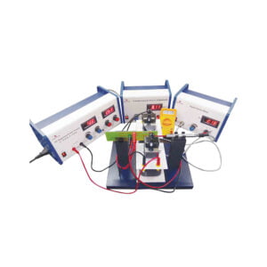
Hall Effect Experiment
Introduction
The resistivity measurements of semiconductors cannot reveal whether one or two types of carriers are present; nor distinguish between them. However, this information can be obtained from Hall Coefficient measurements, which are also basic tools for the determination of carrier density and mobility in conjunction with resistivity measurement.Working
When a conductor through which current is flowing, is placed in the magnetic field, a potential difference is generated between two opposite edges of the conductor in the direction mutually perpendicular to both the field and the conductor. This potential developed is Hall voltage and the phenomenon is called Hall Effect. In the experimental setup, the crystal mounted on PCB is placed perpendicular to the pole pieces. A constant current is passed through the crystal using the constant current source. Magnetic field is produced by electromagnet operated by 0 – 12 V DC, 5 A power supply. Magnetic field intensity is measured by gauss meter with gauss probe. A Hall voltage thus produced is measured by the multimeter.The following parts are included in Hall Effect Experiment:
PH93225H Hall Probe
PH61033D/5 Advanced Power Supply
PH93225E Electromagnet Setup
PH61500 Constant Current Power Supply
PH93225G Digital Gauss Meter
PH64505 3 ½ Digit Multimeter
PH93225 Hall Effect Experiment (Complete)PH93225 -
Electronics
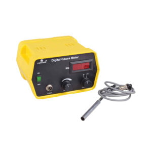
Digital Gauss Meter
Digital Gauss meter works on the principle of the Hall Effect in semiconductors. When a semiconductor with current flowing in one direction is introduced perpendicular to a magnetic field a voltage is produced at right angles to the current path. The magnitude of this voltage is proportional to the intensity of the magnetic field. This voltage is called Hall Voltage. This Hall voltage is amplified and calibrated as the magnetic field.
Specifications:
- Range: 0-2 KG & 0-20 KG.
- Resolution: 1 G at 0-2 KG range.
- Display: 3½ digit LED.
- Power Supply: 220 V, ±10%, 50 Hz AC.
- Transducer: Hall probe-In As.
PH93225G -
Electronics
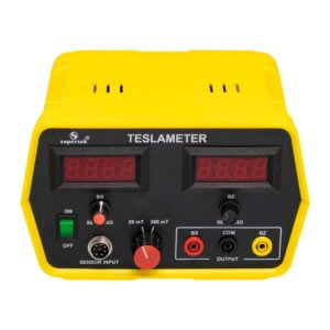
Teslameter
The tesla meter is used for the measurement of flux densities in steady magnetic fields. The unit includes a Hall sensor probe for measuring axial and tangential magnetic fields up to 20mT. The magnetic field probe is provided with a metric scale for measuring distances. In addition to having a digital display, the unit outputs a voltage proportional to the magnetic field which can be measured with a data logger, XY-recorder, or analog multimeter.
PH93240 -
Accessories
Energy Band Gap Apparatus
The energy band Gap Measuring Instrument is used to find the energy band gaps of the different semiconductor diodes and LEDs. The setup comes with a temperature meter, an in-built heating element with an ON/OFF toggle switch, and the following diodes and LEDs (IN4007, Germanium Diode, Green LED, and Blue LED) which can be selected by a rotary switch. Ammeter and voltmeter are connected externally to the instrument.
Specifications
Input Voltage – 12V DC
Current Rating – 5 A Max.
Heater Power – 40 Watt
Temperature Range- 0 – 110⁰CPH94002 -
Accessories
Planck Constant Apparatus
Planck’s Constant Measuring Instrument is used to determine Planck’s constant, “h” using LEDs. The setup comes with a voltmeter, temperature meter, a heating element with an ON/OFF toggle switch, and the following LEDs (Amber, Blue, Yellow, Red, and Green LED) which can be selected by a rotary switch. Ammeter can be connected externally to the instrument.
Specifications
Input Voltage – 12V DC.
Current Rating – 5 A Max.
Heater Power – 40 Watt.
Temperature Range- 0 – 110⁰C.PH94004 -
Electronics
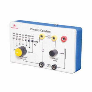
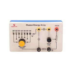
Planck’s Constant
Modern LEDs (light emitting diodes) cover the range from deep blue (440nm) to infrared (940nm). By monitoring the voltage at which each LED just begins to emit light a graph of energy input as a function of light emitted frequency can be plotted and an approximate value of Planck’s constant deduced. Complete with viewing tube but without power supply with stackable lead red 2pcs. & black 3pcs.
PH94005 -
-
Electronics
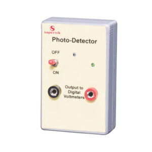
Photo Detector
Photodetector shows that the electromagnetic spectrum extends on either side of the visible spectrum. The detector area is only 1mm dia. so that it can be passed through the visible spectrum produced by a projector and prism. The output is monitored on a multimeter and gives measurable readings from 300nm to 1000nm demonstrating the presence of invisible UV and IR. Requires 9V battery and multimeter with 200mV scale or similar (not included).
PH94010 -
Electronics
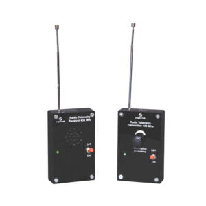
RF Telemetry
Supertek RF telemetry system consists of a radio frequency transmitter and matching radio frequency receiver both operating at 433MHz. The system is designed for radio frequency transmission and reception. The radio frequency transmitter sends out a variable audio signal and the radio frequency receiver with a built-in loudspeaker receives the signal. The system enables the teachers to demonstrate a variety of wave phenomenon. The system also enables the properties of the radio communications to be investigated and compared with those of visible light and other wave motions such as audible sound and water waves etc. For the operation of the system, a 9-volt PP3 battery is required.
PH94020 -
Electronics
Ultrasonic Transmitter and Receiver Set
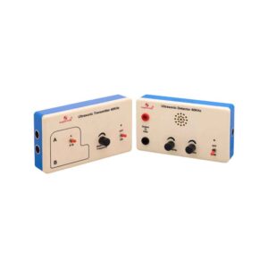
This apparatus consists of a self-contained transmitter and receiver operating in the 40 kHz region. The transmitted wave is modulated at a user-controlled variable frequency of about 2 kHz and this is detected by the receiver which amplifies the signal and drives a miniature integral loudspeaker. Both transmitter and receiver are contained in separate plastic enclosures measuring 175 x 100 x 40 mm which contain all the electronics and the 9 V batteries. The receiver has front panel 4mm sockets so that the output can be monitored on an oscilloscope for more quantitative measurements. The system is ideal for demonstrating sound waves above the hearing threshold and reflection properties associated with sonar etc.
A special feature is the second transducer on the transmitter which can be switched on when required to produce two coherent sources. By moving the receiver along a line parallel to the two sources interference patterns can be dramatically demonstrated simplifying Young’s slits experiment or enabling it to be demonstrated using waves other than light. Complete with batteries, full instructions, and suggestions for use.
PH94022 -
Vacuum Apparatus
Spectrum Tubes
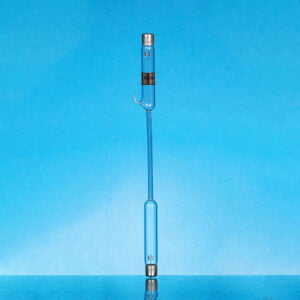
Made of glass, 26 cm long overall, narrowed to capillary width for 8.5 to 10 cm of length. Metal wires holding the electrodes are sealed through the ends and welded to metal caps, which have loops for connecting wires.
For use with Spectrum Tube Power supply PH61025.
PH95014 -
Vacuum Apparatus
Deflection Tube
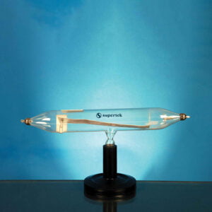
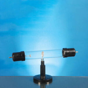
To show deflection of cathode rays by a magnet. Horizontal tube is fitted with a fluorescent aluminium plate, the cathode side of which is bent at right angle and is provided with a slit. Cathode rays passing through the slit cast a sharp and bright shadow across the aluminium plate. When a magnet is brought near, the cathode rays deflect sharply.
*Additional power supply of 12kV is required to operate.
(Not supplied with this product)
PH95035 -
Vacuum Apparatus
Magnetic Deflection of an Electron Beam
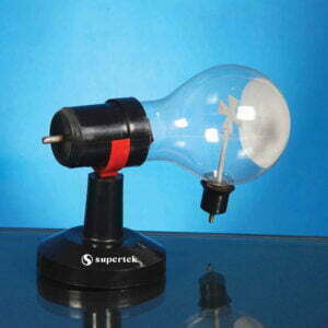
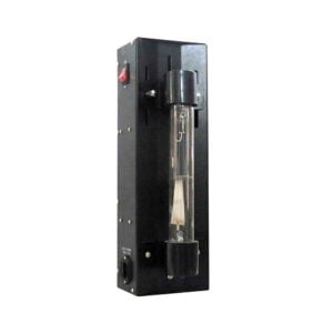
Designed to observe how an electron beam is affected by a magnetic field. The power supply holds a deflection tube with a cathode and an anode. The cathode end features a phosphorous coating, which glows when exposed to electrons. As we bring a magnet (not supplied) near, it causes the electron beam to move in a perpendicular direction to show the deflection of an electron and how a cathode and anode both work.
PH95038 -
Vacuum Apparatus
Canal Ray Tube
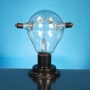
To show positive rays. Vertical type, with two fused discs at each end and a perforated cathode in the center through which canal rays pass. The space below the cathode is filled with characteristic glow of cathode rays and the upper portion has canal rays. A magnet brought near the upper portion will repulse the rays, showing the positive nature of the canal rays.
PH95040 -


